Cold pilger mills for rolling of tubes of hard deformed materials


Mills are intended for rolling of tubes of stainless, heat resistant steels grade and other hard deformed materials with ultimate strength in initial state up to 1100 MPa. Specific features of the tube type production are significant vertical and axial forces during rolling process, high requirements to the accuracy of geometric dimensions and to the surface quality. For production of this tube type, “QUARTO” type mills are recommended.

CPM 40 for rolling of tubes of hard deformed materials

Mills technical characteristic is given below:
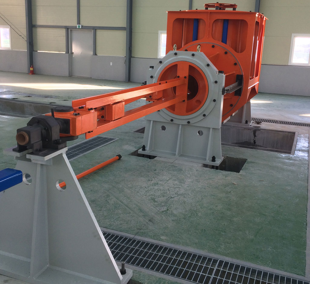
Technical characteristics of cold pilger mills for rolling of tubes of hard deformed materials

Offered mill sizes

Mill size P A R A M E T E R S
Maximum shell diameter, mm Finished tube diameter, mm Finished tube wall thickness, mm Stand stroke, mm Number of double strokes per min., not more Capacity, m/hour Main drive power, кW, not more
CPM 25 25 6-20 0,3-2 360 280 50-200* 40
CPM 40 40 10-35 0,3-3 600 200 30-350* 75
CPM 60 60 16-50 0,4-5 800 180 30-350* 110
CPM 80 80 25-60 0,6-10 960 160 30-300 140
CPM 110 110 40-90 1-12 1160 110 30-250* 210
CPM 150 150 80-120 1,5-15 1300 80 30-200* 450
CPM 200 200 100-180 2-20 1400 70 30-200* 600


* Depending on rolling schedule and quality requirements

Attainment of given parameters is provided by using up-to-date rolling technology with application of lubrication cooling liquid on the base of mineral oil, technological rolling scheme with double turn and double feed as well as rational equipment arrangement and new element basis of new machines.


Design features of main CPM mill assemblies for tube rolling of hard deformed materials


Mill equipment arrangement. Mills for rolling of the tubes with diameter of up to 80 mm are designed with face (axial) charging with two shell chucks and two rod chucks.

Such arrangement provides operation of the mill without stoppage for charging of next shell into the mill. Rolling process without mill stoppage provides quality uniformity of finished tubes and output increasing. When using shell with diameter of more than 60 mm axial rolling forces exceed the possibilities of shell chucks to keep shell without skidding that influences on feed accuracy and decreasing of finished tubes geometrical dimensions. Therefore, for the mills of CPM 80 and bigger size, it is recommended to use arrangement with face (axial) shell charging with one shell chuck with resting against shell face.

Working stand. For tube rolling of hard deformed materials it is recommended a working stand with stationary forced housing and movable roll cassette with working and support rolls.

Rolling forces are taken by stationary housing, therefore, the movable cassette has minimum weight that sufficiently decreases loads on drive of its travel. Strength and rigidity of stationary housing are considerably higher rather than in working stands with movable forced housing that provides high accuracy of rolled tubes.

Furthermore, the stationary housing allowed to mechanize adjustment of rolls position at the rolled tube size being changed manual operations by control from control panel.

Feed and turn mechanism. For the mills with face (axial) charging with resting into shell face in feed and turn mechanism it is used mechanical converter of continuous rotation into impulse rotation of screw and spindles chucks. Feed and turn mechanism is designed on the base of epicyclic crank converter of continuous rotation into intermittent.

Converter of continuous rotation into intermittent movement of feed and turn is made as a epicyclic crank mechanism connected by its driven link to the mill synchronous electrical shaft by means of gearing providing rotation frequency of planet pinions with cranks two times more than number of working stand strokes. For one rotation of planet pinion with crank, the converter driven link gets impulse on 90° within the time of stand drive crank tern on 50-60°. Within the rest time of cycle, the driven link is practically unmovable.

By means of gearing system including changeable gears, impulse transmitted to the screws rotation of which provides movement of shell chucks into given by changeable gears movement of feed within the limits of from 0,5 up to 10 mm per one cycle.

For the mills with face (axial) charging with two shell chucks and two rod chucks as converters of continuous rotation into intermittent it is used programmable control by motors in step mode of operation.

On the Customer request the mills can be designed for maximal shell length of from 5 up to 15 m and with finished tubes receiving tables for length needed in accordance with production conditions.

Drive of cassette movement. Drive of cassette movement is made of planetary-crank type with rectilinear motion of crank with rotating counterweight balancing of dynamic forces and moments system that allows to decrease energy consumption significantly during mill operation.

Cold pilger mills for production of long-length tubes of stainless and other steels


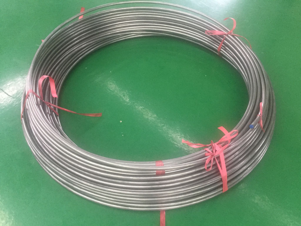
Arrangement. Cold pilger mills for rolling of long-length tubes are equipped with coiling machine that is installed on the rolling line and provides coiling of tubes simultaneously with rolling without stopping of technological process. Coiling machine is installed on the exit side from working stand right after the finish tubes receiving table that allows to roll a normal length tubes and long-length tubes as well.

Technological process. The task of winding the coil out of the tube that is at the same time being rolled inside the working stand is to synchronize the speed of coiling machine rotation with the tube rotation speed, to synchronize the speed of bending rollers rotation with the linear speed of the tube rolling out of the working stand, to synchronize the speed of drip plate movement with the speed of coil heigth increasing. To ensure the stability of machine operation the feedback sensors and strain relief devices are used. Using of the tubes joint sensor allows to determine the time of back end of long-length tube comming out of the working stand and starting of the speed up coiling. Therefore the complete automatization of the winding process is reached. Participation of the operator is required only for removing of the finish coil out of the machine when front end of the new long-length tube is comming out of the working stand and passes through the finish tubes receiving table.

The coiling machine is equipped with special tools for coil removing in order to increase the technological process output and to decrease the labor cost.